Engineering drawing lines types Lines are used to make drawings, but in Engineering Drawing, 12 to 15 Types line all the lines used to make drawings are proposed by the Bureau of Indian Standards (BIS), in engineering drawing, these different types of lines are used for different operations of the object and textures are displayed in Hindi.

Types of line in Engineering Drawing According to BIS
According to Bauru of Indian Standard (BIS) Based on IS 10714 (Part 20): 2001/ISO 128-20:1996, IS 10714 (Part 21): 2001/ ISO 128-21 :1997, ISO 128-22 : 1999, ISO 128-23 : 1999 and ISO 128-24 : 2014
| Type | Description | General Applications | Lines |
|---|---|---|---|
| Type – A | Continuous Thick | A1 Visible Outlines, Object Outline A2 Visible Edges, Object Lines | View Line |
| Type – B | Continuous Thin (Straight or Curved) | B1 Dimension Lines B2 Extension Lines or Projection Lines B3 Imaginary Lines of Intersection B4 Hatching B5 Leader Lines B6 Diagonal Lines B7 Thread Lines B8 Short Centers Lines B9 Outlines of Revolved section in Place | View Line |
| Type -C | Continuous Thin Free Hand | C1 Limit of Partial or Interrupted Views and section, if the limits is not a Chain Thin | View Line |
| Type – D | Continuous Thin (Straight) with Zig – Zags | D1 Lines | View Line |
| Type – E | Dashed Thick | E1 Hidden Edges E2 Hidden Outlines | View Line |
| Type – F | Dashed Thin | F1 Hidden Edges F2 Hidden Outlines | View Line |
| Type – G | Chain Thin | G1 Lines of Symmetry G2 Center Line G3 Trajectores | View Line |
| Type – H | Chain thin, Thick at ends and changes of Direction | H1 Cutting Plain | View Line |
| Type – J | Chain Thick | J1 Indication of Line or Surface to which a special Requirement applies | View Line |
| Type – K | Chain Thin Double Dashed | K1 Centroidal Lines K2 Outlines of Adjacent Parts K3 Parts Situated in Front of the Cutting Plane K4 Alternative and Extreme Position of Movable Parts K5 Initial Out Lines Prior to Forming | View Line |
Types of lines (लाइन के प्रकार)
भारतीय मानक के अनुसार 10 प्रकार की रेखाओं का इंजीनियरिंग ड्राइंग में उपयोग किया जाता है जिनमें से प्रथम चार प्रकार की रेखाएं (A से D प्रकार की) सतत (Continuous)मोटी तथा पतली होती हैं|
बाहरी रेखा (Outline)

यह A प्रकार की रेखा होती हैं, इनका उपयोग दर्शित बाहरी रेखाओ (Visible Out Line) तथा किनारों (Edges) को बनाने में किया जाता है इन्हें वस्तु रेखा (Object Line)भी कहते हैं|
विमांकन रेखा (Dimension Line)

यह B1 प्रकार की रेखा होती हैं, यह पतली तथा सतत रेखा होती है इनके दोनों छोर पर एक्सटेंशन रेखा को स्पर्श करते हुए एरो हेड बनाए जाते हैं इस प्रकार की रेखाओं का उपयोग इंजीनियरिंग ड्रॉइंग की बीमा को प्रदर्शित करने के लिए किया जाता है|
1. लीडर रेखा (Leader Line)
यह B1 प्रकार की रेखा होती हैं, इन्हें तीन प्रकार से प्रदर्शित किए जा सकते हैं
- एक बिंदु के साथ
- तीर के साथ
- बिंदु के बिना या तीर शीर्ष के साथ
2. हैचिंग लाइन (Hatching Line)
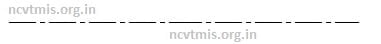
यह B4 प्रकार की रेखा होती हैं, इस प्रकार की रेखाएं तिरछी समानांतर होते हैं इन रेखाओं के मध्य की दूरी को कम से कम उस ड्राइंग की सबसे मोटी रेखा से दुगनी होनी चाहिए एवं 0.7 मिली मीटर से कम किसी अंतराल में नहीं होनी चाहिए|
शॉर्ट ब्रेक लाइन (Short Break Line)
यह C1 प्रकार की रेखा होती हैं, यह रेखा पतली सतत तथा मुक्त हस्त वक्र रेखा है जिसके द्वारा किसी ऑब्जेक्ट को की अनियमित बाउंड्री व उसकी ड्राइंग को कम दूरी तक तोड़ कर दिखाया जाता है|
लॉन्ग ब्रेक लाइन (long break line)

यह D1 प्रकार की रेखा होती हैं, यह पतली सतत रेखा दो या तीन जगहों पर ज़िग ज़ैग आकार में बनी हुई होती है इसका उपयोग ऑब्जेक्ट के किसी लंबे भाग को ड्राइंग में कम स्थान में दिखाने के लिए किया जाता है|
बिंदुकित अदृश्य रेखा (Dotted Hidden Line)
यह E2 अथवा F2 प्रकार की रेखा होती हैं, इसका उपयोग ड्राइंग में ऑब्जेक्ट के छुपे हुए भाग को दर्शाने मैं किया जाता है|
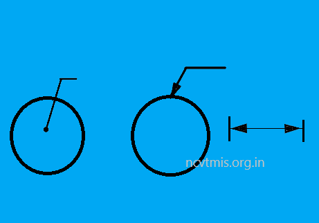
केंद्र रेखा (Centre Line)
यह G2 प्रकार की रेखा होती हैं, इसका उपयोग वृत्ताकार वस्तुओं या वृत्त आदि के केंद्र प्रदर्शित करने के लिए किया जाता है इसे एक क्रमशः लंबे ड्रेस तथा एक छोटे ड्रेस को खींचकर बनाया जाता है|
Thickness of Engineering Drawing Lines
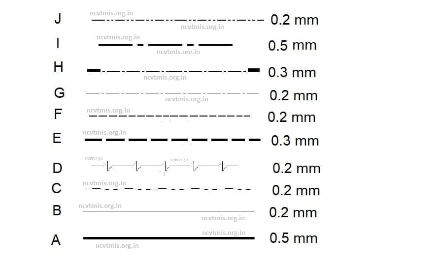
रेखाओं की मोटाई का चयन ड्राइंग के प्रकार तथा नाप के अनुसार 0.18 0.25 0.35 0.5 0.7 1.4 तथा 2 मिलीमीटर की परास में किया जाता है एक ड्राफ्ट्समैन द्वारा 0.5 मिलीमीटर परास की रेखाओं का अधिक उपयोग किया जाता है|
Some Important Line FAQ
What should be the distance between hatching lines?
The distance between hatching lines should not be less than 0.7 mm at any interval.
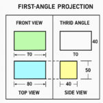
- 1st angle and 3rd Angle Projection आसान भाषा में
 बेसिक समझ – Orthographic Projection क्या है? किसी 3D ऑब्जेक्ट (त्रिआयामी वस्तु) को जब हम 2D (दो आयाम) में दिखाते हैं,यानि उसकी लंबाई (Length), चौड़ाई (Width) और ऊँचाई (Height) को अलग-अलग दृश्यों (views) में दिखाते हैं,तो उसे Orthographic Projection कहते हैं। इसमें हम मुख्य रूप से 3 views बनाते हैं: Principle Planes (मुख्य तल) Orthographic … Read more
 - Isometric और Orthographic Projection को आसान भाषा मेंसबसे पहले समझो – ये दोनों क्या होते हैं आइसोमेट्रिक प्रोजेक्शन (Isometric Projection) और ऑर्थोग्राफिक प्रोजेक्शन (Orthographic Projection) — दोनों ही तकनीकी ड्रॉइंग में अत्यंत महत्वपूर्ण हैं। ड्रॉइंग बनाते समय कुछ सावधानियाँ ज़रूरी हैं — जैसे कोण सही रखना (30°), प्रोजेक्शन लाइनें समान रखना, सही स्केल का उपयोग करना, और छिपी रेखाएँ (Hidden Lines) ठीक ढंग से दिखाना। 1. Isometric Projection (आइसोमेट्रिक प्रोजेक्शन) यह … Read more
- ITI AITT CITS Important Engineering Drawing Model Paper 2023Latest Model Paper of Engineering Dawing According to the latest NIMI Pattern Most Important Question and with Solve for ITI Engineering Drawing. All India Trade Test of Craftsmen, Model Paper Set – 1 ENGINEERING DRAWING इंजीनियरिंग ड्राइंग First Year (प्रथम वर्ष) – 2023 Q1. Print 10mm Single Stroke capital letters and numerals in inclined style. … Read more
- Important Engineering Drawing Symbols GraphicsEngineering Drawing Symbols for Drawing Students according to BIS Rule 46-2003 all symbol used in all types technical drawing Sector Like – Engineering Diploma ITI etc. this Symbols also used for Engineering Graphics. Rivet Joints Convection Symbols Description View in Drawing 1st Angle 3rd Angle Rivet or Bolt to fit on site Rivet General Rivet … Read more
- Engineering Drawing Question Paper in HindiMost Important Engineering Drawing Question Paper 2022 for ITI Introduction of Engineering Drawing Question answer all Question are Important for ITI CBT Exam Engineering Drawing Question Paper with Answer